November
2016
HYDROCARBON
ENGINEERING
76
electrical energy, so that a predefined temperature
differential is always maintained between the two
sensors. For example, 50˚C (122˚F) is the constant
temperature differential for most thermal mass flow
meters (Figure 1). As soon as the fluid flow begins, heat
is drawn from the heated velocity sensor via the gas
molecules flowing past. The heat is dissipated as it is
carried off by the flow. As the gas molecule flows past
the sensor, it heats up and carries this heat away with it
downstream.
The corresponding cooling effect is measured and
compensated for instantaneously by the instruments’
sensor drive electronics, which instantly adds more
heating current to the sensor to maintain that constant
temperature differential of 50˚C (122˚F). Figure 1 shows
that the gas molecules themselves transfer the heat. In
a real world flow application, all of this happens in a
millisecond continuously and never stops. In essence, a
thermal mass flow meter is counting molecules that
flow past, heat up, then take the heat away with them
and carry it downstream – as a result, extremely
sensitive, accurate and repeatable molecular mass flow
measurement occurs.
Now that the basic measurement principal has been
described, how is total mass flow rate of gas flowing
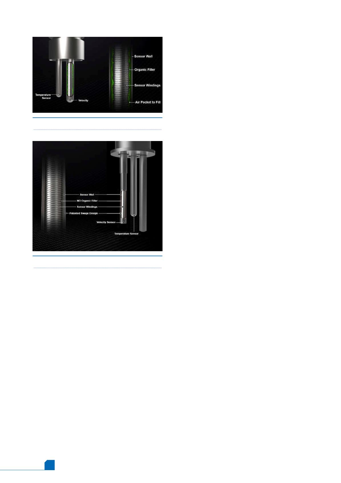
Figure 3.
Wet sensor design.
Figure 4.
Dry sensor design.
through the pipe actually calculated? As described
by King’s law, the heating current required to maintain
the constant temperature differential between the
two sensors is proportional to the cooling effect
caused by the gas molecules flowing by, and,
therefore, is a direct measurement of total gas mass
flow rate in the pipe. It is important to note that
heat transfer from flowing gas is affected by the
properties of the gas.
These are known gas properties, such as:
n
n
Thermal conductivity.
n
n
Density and viscosity.
n
n
Heat capacity.
Innovation opens doors
Traditional thermal mass flow meters have limitations
in gas sampling applications because they cannot
accurately measure low flows with changing gas
composition without factory recalibration.
However, recent innovations in thermal mass flow
sensor technology have removed this barrier. Adding
two more temperature sensors has given rise to the
next generation four-sensor ‘quad’ thermal mass flow
meters and now combine robust construction with
extreme sensitivity – improving accuracy and
turndown (Figure 2).
Compared to previous generations of ‘two-sensor’
thermal mass flow meters, the maximum flow rate
has tripled with quad thermal flow meter technology.
Even more notable is the improvement in the
minimum detectable flow rate. An entirely new
‘ultra low flow’ market has opened up for industrial
thermal meters and now, for the first time, quad
thermal flow meters can manage changes in gas
composition through on board gas mixing software in
the field.
Accuracy specifications are comparable to
coriolis meters at a much more economical price.
Pioneered by Sierra Instruments, Inc., based in
Monterey, California, quad thermal (QuadraTherm®)
has a
±
0.75% reading accuracy for insertion probe
versions (an improvement on the 2% of reading
previously possible with traditional thermal
technology). The in-line version of the instrument
improves on that with
±
0.5% of reading accuracy.
These new advancements make quad thermal
technology ideal for gas sampling applications.
Dry thermal sensor technology: the
key to sensor stability
Many traditional thermal dispersion flow meters
have ‘wet’ sensors that have heat lost via stem
conduction that is not accounted for and can
introduce errors as high as 20%, depending on the
gradient between the gas temperature and the
temperature outside of the pipe. This is because of
the organic potting cement used in ‘wet’ sensors that
will shift and crack over time (Figure 3) causing
unwanted sensor drift, and resulting in a gradual
degradation of flow measurement accuracy.


