November
2016
HYDROCARBON
ENGINEERING
72
conditions. The simulated flames from the Galaxy
burner are predicted to be at 85% of the radiation
fence height.
Testing and conforming
The exit velocity from pressure assisted flares is too
high to meet US EPA design guidelines for flares
(40 CFR 63.18). To use pressure assisted flare technology
in the US, one must file for an Alternative Means of
Emissions Limitation (AMEL). The filing process includes
a provision that ‘each owner or operator applying for
permission shall be responsible for collecting and
verifying test data for an alternative means of emission
limitation to test data for the equipment, design and
operational requirements (40 CFR 61.244)’. Adherence
to local regulations and good work practices drive the
use of physical testing for other locales.
The Galaxy multipoint flare burner has been
pre-tested across a wide variety of common vent gas
compositions, including those that have high nitrogen
concentrations. The average destruction and removal
efficiency (DRE) across a range of vent gas
compositions, including those with high inert
components, was 99.87%.
Robust design
The Galaxy burner is made from cast high alloy steel
and is a single-piece design with no welds in the heat
affected zone. This design modification has been made
based on industry experience after the failure point of
many types of multipoint flare burners occured where
welds had been made to either attach arms to a spider
burner, or to affix a top-plate to an open casting.
Figure 6 shows the results of a fluid-structure
interaction study that was carried out to confirm the
burner’s robust design. The maximum thermal stress
induced falls well below the failure point of the
material, even under the continuous steady-state
operation of a single burner at maximum flow rate.
Maximising the results
An increased smokeless turndown capability, improved
burner cross-lighting, reduced specific flame length per
unit of vent gas flow, and high vent gas destruction
efficiency, afford many system-wide design
improvements.
The burner count for the flare system can be
reduced due to the increased smokeless turndown
capability, improved cross-lighting and shorter flame
length. A lower burner count results in a reduced spare
parts requirement, decreasing the initial capital
expenditure and the operating cost of the flare system.
A shorter specific flame length per unit of vent gas
flow can also use a shorter radiation fence. The Galaxy
burner flame length does not increase in multi-burner
installations to the same degree as previous generation
burners, allowing for a more reliable flame tip location
relative to the top of the flare fence. In addition to the
reduced material cost of a shorter fence, the reduced
weight results in reduced foundation requirements.
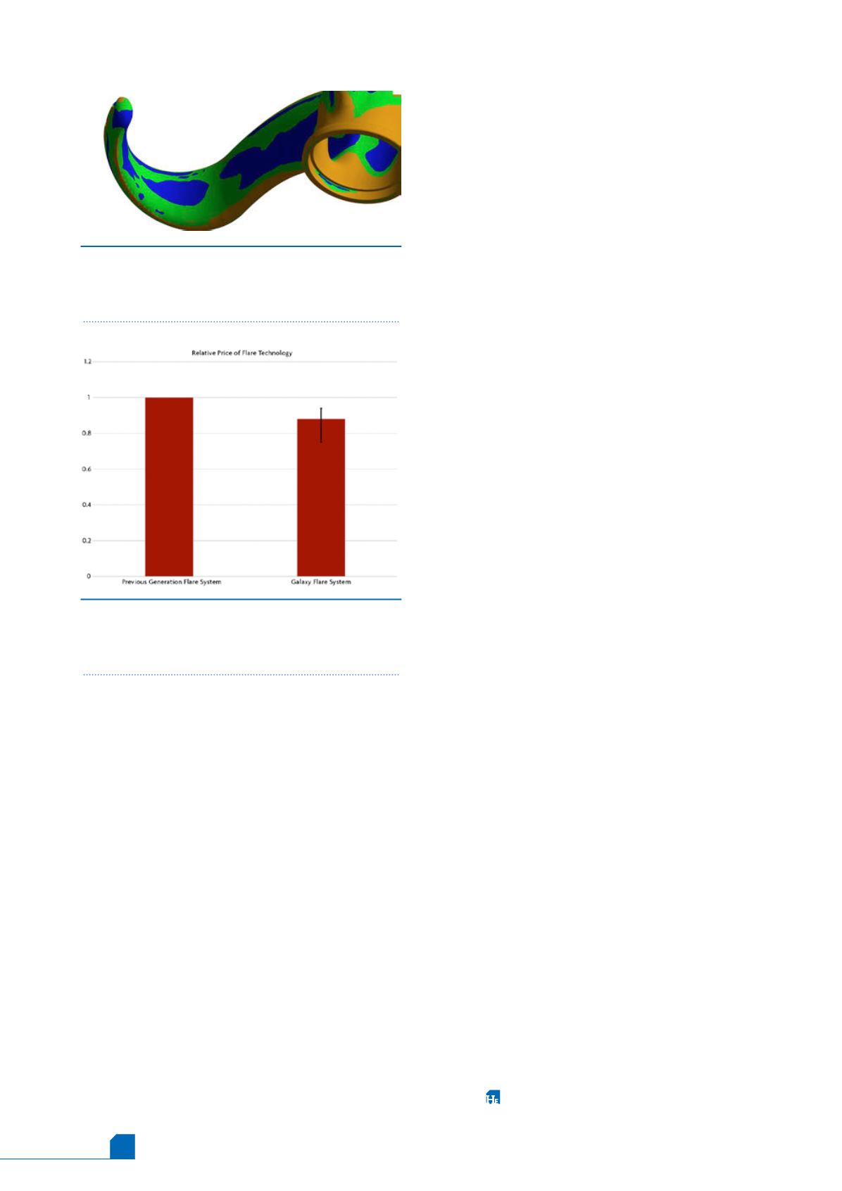
Figure 7 shows the potential reduced cost of using
the Galaxy flare system. In addition to a superior
technical solution, which was pre-tested against a
variety of vent gas compositions, the additive
improvements resulted in cost savings of 6 - 25%,
depending on the configuration selected.
Conclusion
By using advanced design tools such as CFD and FEA in
conjunction with full scale physical testing in the
Callidus test facility, the Galaxy multipoint flare burner
was created. This new generation of flare burner has
improved cross‑lighting capabilities, shorter flames in
both single and multiple burner applications, has been
pre‑tested in accordance with previous EPA AMEL
requirements, and has a robust design for use under
high flow conditions. These features combine to
provide a more valuable system design, which has
reduced noise during lighting events, fewer
components to purchase and maintain, a shorter flare
fence, and reduced foundation requirements. The
higher performance of this lower cost system is
demonstrated by extensive physical testing, advanced
simulation, and statistical analysis of the
results.
Figure 7.
The relative price of a Galaxy flare system
to the previous generation of technology. A 6 - 25%
reduction in cost is possible depending on the
selected options.
Figure 6.
Safety factor plotted against the cast arm of
a Galaxy flare under development. The thermal stress,
fluid pressure and mechanical loads were combined in
the analysis to confirm the design.


