November
2016
HYDROCARBON
ENGINEERING
74
Natural gas sampling challenges
In order to comply with state and federal regulations,
oil and gas companies need to take an adequate gas
sample that is representative of the gas flow. This
requirement to take a ‘representative sample’ is
challenging for engineers. They must first carefully
consider where to take this ‘representative’ gas sample
from the source stream. The most accurate
representative samples cannot be taken from a ‘dead
leg’ or an area of heavy flow disturbance. In addition,
the sample’s chain of custody must be maintained in
order to avoid contact with other contaminants.
Engineers must also reduce and control the pressure to
the analytical tool, stabilise and control the flow, all
while protecting the analytical instrument from
particulates, moisture and pressure/flow excursions.
Engineers must take the gas sample in as real time
as possible, so that it correlates with actual process
flow. With these gas sampling application challenges,
the goal for oil and gas engineers is to take the most
accurate gas flow sample, as quickly as possible, and
with the lowest incurred cost.
Figure 1.
Thermal dispersion mass flow.
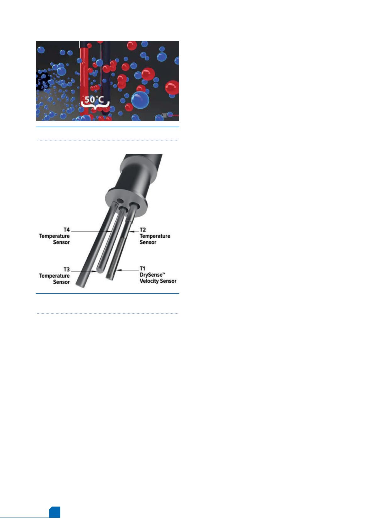
Figure 2.
Advanced four-sensor QuadraTherm thermal
sensor.
When the optimal gas sampling location has been
determined, there are still other inherent flow
challenges to consider:
n
Wide flow rate variations: turndowns of up to
1000:1 may be required.
n
Changes in gas composition – wide gas density
variations: traditional flow meters cannot
successfully manage changes in gas composition
and still maintain accuracy.
n
Non-uniform flow profile: gas measurements
generally have asymmetric and swirling flow.
n
Very low pressure with variable temperature:
most lines operate near atmospheric conditions
with gas temperatures that vary with the gas
source.
A lack of solutions
There are various analytical tools on the market
today that attempt to meet all of the above gas
sampling and flow metering application
requirements. Gas chromatographs are still the most
common tool, while new micro-analyser systems are
gaining wide acceptance. A common thread in all
such analysers is that the gas sample flow must be
precisely measured and controlled, remain
independent of pressure and temperature variations,
and measure over a fairly wide range of flows at
various compositions. In reality, it is not possible to
have the flow rate unaffected by pressure and
temperature variations.
Common technologies, such as averaging pitot
tubes and insertion turbine meters, demonstrate poor
performance in gas sampling applications. These
devices measure volumetric flow, not mass flow,
where mass flow is the required measurement. They
also require a clean gas with constant gas
composition. Additionally, they often cannot measure
down to the low flows some gas samplers require. As a
result, these technologies do not effectively provide
the precise ‘representative sampling’ data required to
meet government regulations.
There is, however, a new technology innovation
based on the thermal dispersion principal that meets
these challenges. This technology will be examined
in detail below.
Thermal mass flow meter principle of
operation
As the name implies, thermal dispersion mass flow
meters use heat to measure flow and are the only
other direct mass flow meter in existence, along with
coriolis. Thermal technology has a major cost
advantage over coriolis, being on average one fifth of
the cost. Insertion probe thermal meters can be as
much as one tenth of the cost for larger pipes.
As thermal is direct mass flow, there is no need
for secondary measurements and flow computing to
calculate mass flow. With thermal technology, mass
flow rate is direct and unequivocal.
Thermal mass flow meters have no moving parts.
The velocity sensor is heated continuously via


