November
2016
HYDROCARBON
ENGINEERING
68
additional benefit of reduced heat load on the flare
components due to adequate vent gas and air mixing even
at low flows.
The de-staging pressure is the minimum operating
pressure of the flare system for which smokeless
performance should be expected. Figure 2 shows a
process capability chart for the Galaxy flare burner’s
smokeless performance as a fraction of a typical
staging pressure. The upper specification limit, or the
de-stage pressure, is designated on the right side of the
graph with a normalised value of 1. The maximum
operating pressure that produced smoke for any vent
gas tested was 42% of this de-staging pressure.
Accounting for the variability among the tested
vent gases, there is a 0.01% (122.87 ppm) chance of
visible smoke across vent gas types during a de-staging
event. The probability of visible smoke from the Galaxy
flare burner is less than the statistical analysis suggests,
given that the most common type of vent gas that
produces the most smoke is contained within the data
set at 42% of the de-stage pressure. Although visible
smoke could occur near the burner, it still may not rise
above the flare fence before dissipating. The Galaxy
burner produces essentially no visible smoke for any of
the vent gas compositions tested.
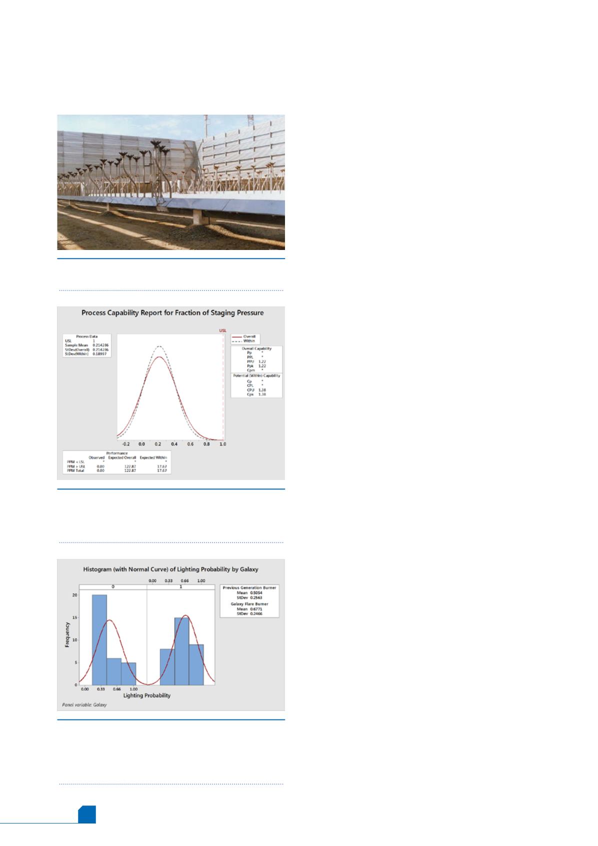
Improved burner cross-lighting
A typical multipoint flare stage may have between five
and 50 burners attached to a single pipe manifold.
When a stage is placed in service, a continuously
burning pilot ignites a flare burner. The flame then
propagates – or cross-lights – the row of burners
comprising a stage. If there is a delay in the lighting of
the burners, a higher volume of combustible vent gas
will accumulate near the burner heads before ignition
occurs, potentially resulting in an audible pressure
wave during the ignition event.
To reduce the ignition delay between flare burner
heads, cross-lighting ports can be used to direct ignited
vent gas to the adjacent flare burner head. For vent gas
with a large inert mixture component or low flame
speed, the size of the ports required for cross-lighting
may disturb the air ingress and mixing between the
flare burner heads under full load, which could cause
flames to rise above the radiation fence.
Additionally, a large portion of the heat may be
released directly adjacent to the burner heads,
reducing their life either through direct heating or coke
production from the heated vent gas inside the burner
heads.
Another common solution to decrease the time
delay in cross-lighting is to move the flare burner heads
closer together along the length of the vent gas
distribution manifold. For older burner designs, the
combined flame of multiple burners operating at high
capacity would often be visible above the flare fence.
However, the Galaxy multipoint flare burner was
designed from inception to operate as part of a large
flare system while maintaining short flame lengths.
Figure 3 shows test data with the probability of full
ignition of a group of burners within less than one
second of a highly inert vent gas flow arriving at the
first burner. The left panel represents the test data
Figure 1.
A typical multipoint ground flare viewed
from the inside of the radiation fence.
Figure 2.
Probability of visible smoke during a
turndown (de-staging) event presented as a process
capability report. There is a 122.87 ppm chance of
visible smoke, given the data.
Figure 3.
Probability of ignition within >1 sec. for a
group of multiple burners. The left panel shows the
previous generation of flare burners while the right
panel shows the Galaxy flare burner. A higher number
means shorter ignition time.


