November
2016
HYDROCARBON
ENGINEERING
54
their opinions on the ‘best in class’ approach to this
important feature.
The overall universal opinion was that PST is only
of use if the information obtained is both accurate
and acted upon. Essentially this means that if a
problem arises, operators need to take action before
the problem can escalate into a serious operational
issue.
To meet the specific operating requirements as
stated by the instrument engineers, Paladon Systems
embarked on designing its own smart PST device, the
PST Controller. When the HIPPS is first commissioned,
a PST is initiated and various parameters such as the
valve actuators’ operating pressures and valve stroking
times are recorded – either on the controller internal
memory, or they are sent to an external storage
device. Collectively, these parameters are called the
HIPPS signature. By recording the HIPPS signature
when the system is first installed and, therefore, when
it is operating at optimum performance, any future
PST can be compared to the signature to identify any
deviations in the parameters. Operators can easily
observe any deviations and trends in the parameters
and take preventative maintenance activities well
before the HIPPS’ performance is compromised.
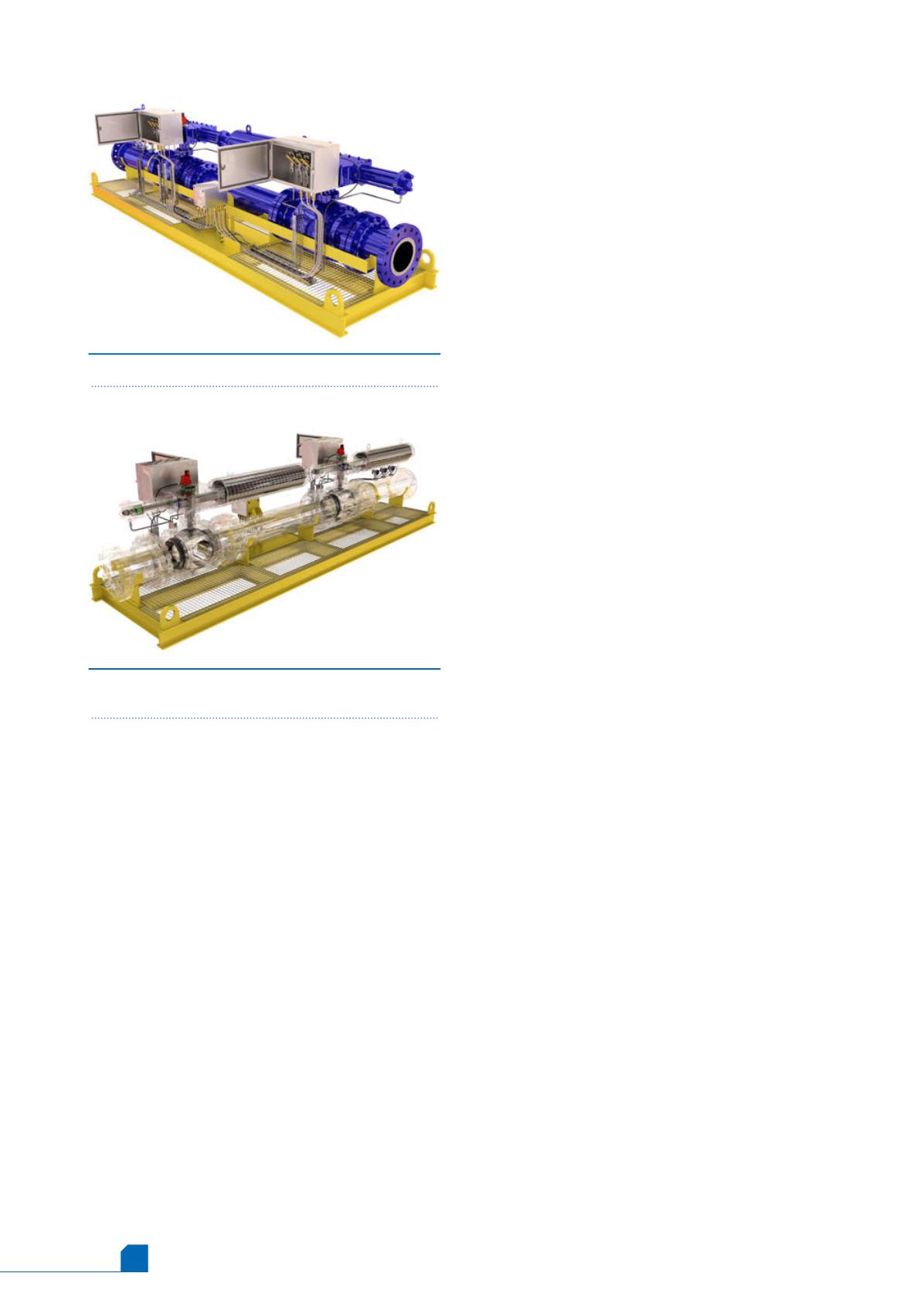
Figure 4.
A typical skid mounted HIPPS assembly.
Figure 5.
HIPPS assembly showing the internal
components of the block valves and valve actuators.
Although many HIPPS suppliers use one of the two
emergency shutdown (ESD) solenoid valves for PST, it
should be recognised that PST is a maintenance issue
and not an ESD one. As such, leading HIPPS suppliers
will isolate the PST from the ESD function, whilst
ensuring that any ESD operation will always override a
PST.
The fundamental reason for separating the PST and
ESD functions is that the operating times necessary for
each function are very different.
Many ESD operations need to be completed in two
seconds, or even less. Considering that during an ESD
event a block valve is always closed on the valve
actuator’s spring stroke, the block valve closing speed
is determined by how quickly the ESD solenoid valves
can vent the hydraulic fluid from the valve actuator’s
hydraulic cylinder. To achieve rapid block valve closure,
ESD solenoid valves have to support very high volume
flow rates.
A typical PST will close a block valve about 10 - 15%
of its total travel before fully reopening it. If an ESD
solenoid valve is designed to fully close a block valve in
two seconds during an ESD operation, and is also used
for PST, then the solenoid valve would close a block
valve by 10% in only 200 milliseconds during a PST. Such
a rapid PST not only makes it very difficult to accurately
record any parameters, but also carries the real risk of
over‑running the 10% block valve closing position –
upsetting the process conditions at best, and completely
closing down an entire installation at worst.
By separating the ESD and PST functions, PST can be
conducted at a far more controlled time to avoid the
above issues.
The question then arises as to how a check can be
made on the solenoid valves used for the ESD function.
In reality, and as two valves are used for SIL 3 certified
HIPPS, this testing should not be necessary, particularly
if these valves are fitted with a manual reset function.
However, if ESD solenoid valve testing is required,
advanced smart PST devices allow the ESD solenoid
valves to be pulsed to check for solenoid valve
operation without disturbing the rest of the system.
Interlocking manifold assembly
This assembly comprises three two wire electronic
pressure transmitters (4-20Ma) with a 2003 voting
system, with communication to the logic solver. The
pressure transmitters will have self-diagnostics and be
programmed to signal a specific failure position.
Logic solver
The logic solver can be either a solid state
programmable logic controller (PLC) or hard wired
relay logic. They are responsible for processing the
various signals on the basis of preset information and
signals from the pressure transmitters and any other
devices, as required by the safety analysis and cause
and effect logic, to determine when to initiate
shutdown of the block valves. To prevent spurious
closure of the block valves and the resulting costly loss


