


 38 / 76

July
2020
HYDROCARBON
ENGINEERING
36
production in the region that stretches across West Texas and
south eastern New Mexico, the Environmental Defense Fund
(EDF) found that approximately one in ten flares was unlit or
malfunctioning. Surveying more than 300 sites, the EDF’s
preliminary estimates indicated that unlit or faulty flares were
responsible for more than 10% of the Permian’s methane
emissions – far more than previously thought – and making it
clear that flaring issues and methane emissions are inextricably
intertwined.
While COVID-19 has slowed down certain segments of the
oil and gas refinery industry and reduced investments in
process optimisation and digital transformation technology,
investments are still being made in flare monitoring and other
safety systems, which are one of the last budgets to be cut.
This is particularly true as regulatory pressure to monitor flares
increases and dependable pilot monitoring signals are required
to ensure reliable flare status records.
At a time when budgets are being highly scrutinised,
refineries can comfortably make investments in flare pilot
monitoring to ensure these systems are future-proof and can
support longer-term investments in digital transformation and
Industry 4.0 initiatives. This article outlines those top
considerations for ensuring compliance and safety today,
while optimising for tomorrow’s digital transformation.
Redundancy for reliability: critical
system needs to be redundant
Accurate flare operational status monitoring is critical to safe
facility operations and require an accurate confirmation during
100% of flare operations. In order to ensure monitoring
redundancy, more than one method of flare monitoring
systems must be used to meet safety and governmental
monitoring requirements. The use of multiple flare monitoring
solutions and technologies can offer the facility a more
reliable flare status and create a redundant robust flare
monitoring solution. If one system/solution fails, having a
redundant monitoring solution take over as the primary
monitoring solution for these times between a flare
maintenance turnaround and the failure of a primary flare
monitoring solution allows the facility to meet its operational
planned turnaround schedule – without having to make
unplanned costly flare shutdowns for emergency repairs.
Multiple sensors
It is advised to use different methods and types, as one will
work better in condition A. For example, thermocouples for
flare pilot monitors are normally part of standard original
equipment manufacturer (OEM) flare supply. While
thermocouples for pilot monitoring work well and are not
normally affected by weather, they are subjected to thermal
shock. Low-temperature pilot flame cycling to large
high-temperature flaring events, then back to low-temperature
pilots, creates a thermal shock to the thermocouple, creating
premature failures. In condition B, infrared optical monitoring
may work best.
Pyrometers
‘Infrared pyrometer’ pilot monitors have been available for
over 25 years and offer a remote monitoring solution that is
not affected by the flare’s process heat. These can be
installed without the need to remove the flare from
operation by installing the infrared pyrometer at ground level
or at a remote level on infrastructure that provides a visual
sight line to the flare tip pilots. Pyrometer systems usually
offer an analogue-switched mA output representative of the
pilot status and/or a relay. Both these standard switched
outputs should have a delay timed to a minimum of 1 minute
to reduce false alarm signals to control room operators to
compensate for short-term loss of pilot signals due to
weather, wind or passing personnel temporarily blocking the
pyrometer’s view of the flare tip. An additional higher end
capability for the pyrometer is the flame intensity mA
output that provides a real-time flame size output by
Figure 1.
FlareSpection thermal imaging installation
in a multiple flare tip application.
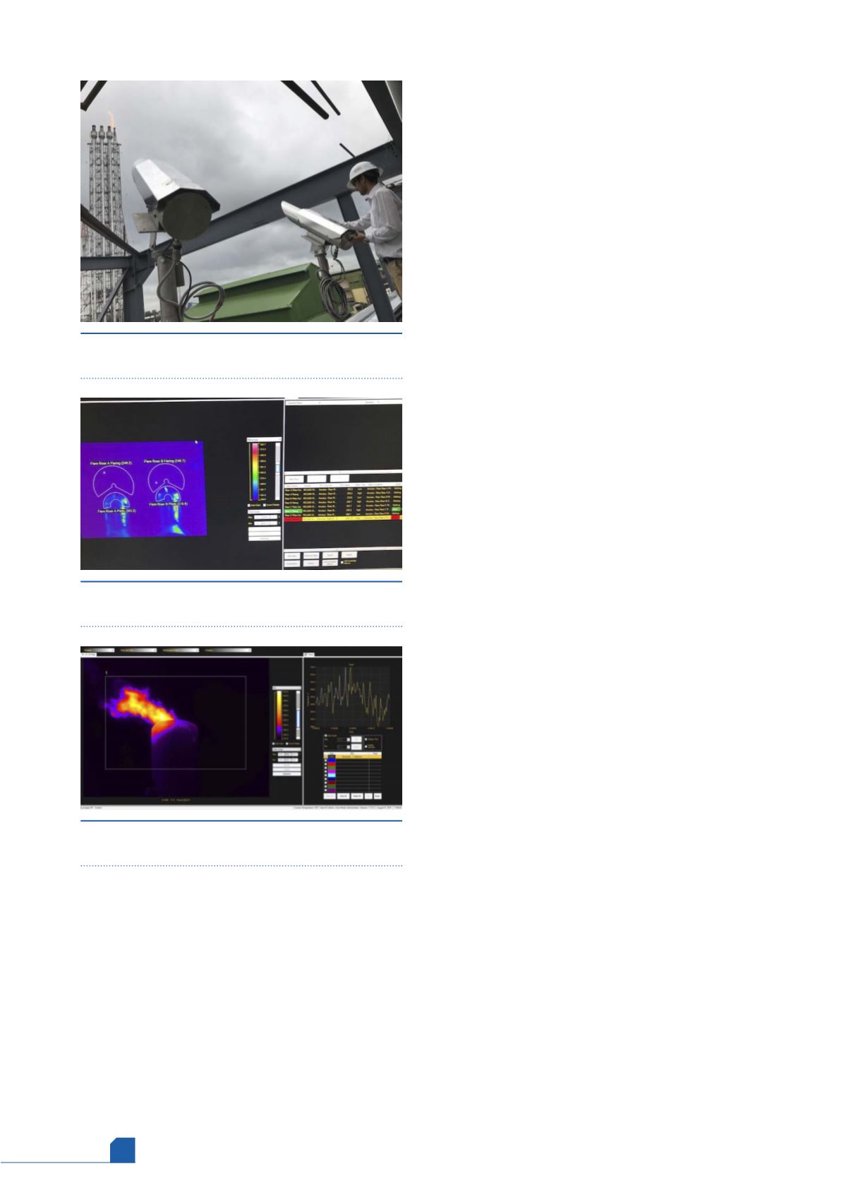
Figure 2.
LumaSpec RT flare monitoring software
using pilot and flaring regions to trigger flare status.
Figure 3.
LumaSpec RT flare monitoring software’s
flaring analysis capability.