


 36 / 76

July
2020
HYDROCARBON
ENGINEERING
34
available, a pressure boosting system can be used to provide the
necessary high pressure. A multistage gas pump (compressor) is
used to charge an accumulator, which is used to prime the
launcher unit. A systemworking off only N
2
bottles will not
require a booster pump, reducing overall capital investment.
The pellet system design includes an accumulator for storage of
propellant gas in case the supply source fails.
To reduce maintenance and provide reliable spark, all
electronics and movable parts, including the ignition panel, are
mounted in the launching cabinet near the base of the flare. A
small-bore guide pipe in material SS 316L runs from the ignition
panel to the tip. The top 5 m of this pipe should be SS 310S
material to resist high temperatures. To ensure there is no
moisture build up in the guide pipe, the system is designed with
a continuous air purge.
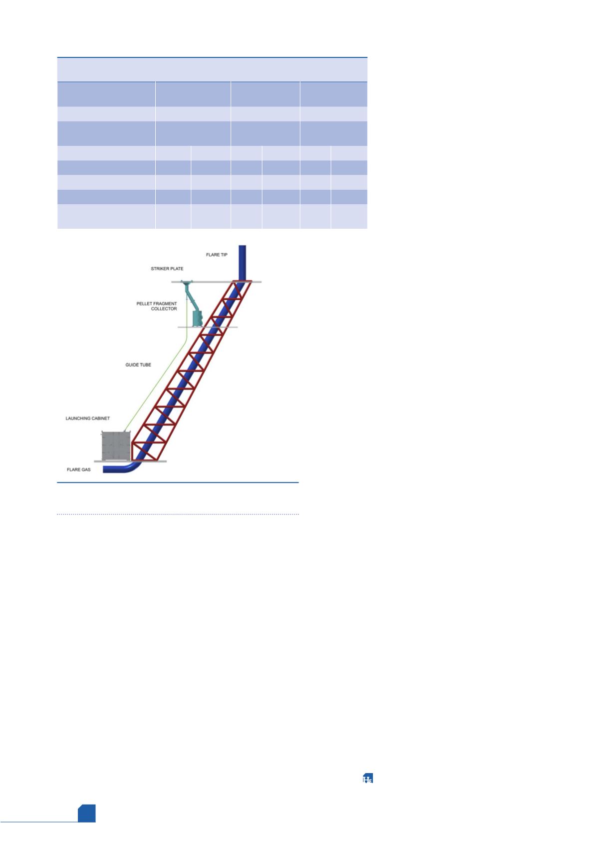
An ignition unit at the tip directs the spark shower from the
pellet striker plate towards the flare tip ignition zone. The
fragments from the used pellets are retained within the ignition
unit and allowed to fall down a chute to a galvanised carbon
steel fragment collection bin on a lower platform.
The system has capacity to launch three pellets within quick
succession, with the normal designed process set to launch one
pellet per on-demand ignition. The pellets
are loaded into a magazine which
automatically indexes after each pellet
launch to load a new pellet, and the system
includes several operational checks to
provide feedback to the operator.
Advantages for zero
routine flaring
When transitioning to a pellet ignition
system in place of traditional flare pilots,
significant emission reductions can be
achieved. Comparing Table 1, flare type
comparison continuous emissions to those
shown in Table 2, with the pellet ignition
system, changing the method for flare ignition results in
anywhere from 119 917 kg/yr reduction in emissions to
449 688 kg/yr, depending upon the type of flare and number of
pilots replaced. As part of an overall programme to achieve zero
routine flaring, pellet ignition systems can be combined with
Flare Gas Recovery (FGR), liquid seals, and vapour recovery to
dramatically reduce emissions (see Table 3).
Although the concept of FGR appears simple, it is a critical
package directly connected to the flare and the two should be
viewed as a single system. The improper design of a compressor,
recycle system, or liquid seal drummay result in air being pulled
back into the flare header through the flare tip. This can
produce an explosive mixture in the flare or flare header,
resulting in a flashback and equipment damage.
Applications
While the ZIP system has benefits as part of a gas recovery
package, it can also be used to improve safety in many other
flaring scenarios. Where an operator’s pilot ignition system has
failed, the system can be an easy retrofit to resolve ignition
problems. Where an operator is using a flare pistol to ignite a
flare, the system can be installed to replace this
non-recommended practice, providing a safe ignition
alternative. In remote locations where power and fuel gas are
not available or where well testing is routinely required, the
system can be used for safe and reliable ignition. Even where a
pilot system is used as a primary ignition method, the system
can be installed as a simple and low-cost backup.
Another advantage of high pressure pellet ignition systems
is that they are compatible with extreme temperatures.
Installed base today includes Arctic Circle operations that
must withstand temperatures of -21.7˚C, ice formation, and
potential heavy snow. As discussed in this article, the system’s
basic operating principle is that the flares will be closed,
meaning no routine flaring and no pilots in continuous
operation. In an emergency, the pressure of the flare gas in the
flare header will initiate a pellet launch. The system timings
are established during commissioning to ensure the arrival of
the pellet and the flare gas coincide at the tip. Simultaneously,
the pilot gas valves are opened to allow pilot gas to flow to
the pilots. The sparks from the pellet striking the striker plate
lights the main flame, and the main flame in turn ignites the
pilots. The pilots then maintain the main flame during the
flaring event. Once the flaring event is over, the pilots are
extinguished.
Table 3.
With Flare Gas Recovery (FGR)/liquid seal/vapour recovery
and pellet ignition system
Flare system
Single 60 in. high
capacity steam tip
Staged multipoint
ground flare
Two 48 in. VariJet
flares
Number of pilots
0
0
0
Annual purge gas
consumption (Nm
3
/yr)
0
0
0
Annual emissions (kg/yr)
NO
X
CO
2
NO
X
CO
2
NO
X
CO
2
Pilots
0
0
0
0
0
0
Purge
0
0
0
0
0
0
Steam generation
1074
1 832 630 0
0
0
0
Total annual continuous
emissions (kg/yr)
1074
1 832 630 0
0
0
0
Figure 2.
Diagram of the ZIP ignition system as installed
on a typical flare boom.