


 40 / 76

July
2020
HYDROCARBON
ENGINEERING
38
offering a low mA output for pilot detection and a high mA
output for flaring indication. This flame intensity mA output
allows for facilities to set up separate mA level setpoints for
a pilot condition and a higher mA setpoint to indicate a
confirmation of a flaring event.
Thermal imaging
The use of high-resolution ‘thermal imaging’ solutions is now
able to provide more than just flaring detection. Thermal
imaging systems can offer reliable individual pilot detection
and through the software provide pilot status confirmation
and alarms. Thermal imaging offers a solution for
applications with fog conditions where the older pyrometer
solutions have had issues. Thermal imaging solutions can
monitor multiple flare tips in close proximity and detect
flaring interference from adjacent tips of pilot flames, as well
as staged flare systems for stage confirmation for the
operator and gas assist flares to ensure the correct flaring
flame size, which ensures that the high carbon monoxide
(CO) gas stream has enough assist gas to maintain the flaring
event and not too much assist gas is being used, which
would increase operational costs.
Use and/or logic to reduce false alarms
in optical solutions
The use of redundant installations of pilot monitoring
solutions can solve false alarms due to very extreme weather
conditions. A single optical monitoring solution has a higher
false alarm potential in very extreme weather conditions
than having a multiple flare monitoring solution installed.
Adding more than one optical flare pilot monitoring solution
in separate locations and pooling them and only alarming if
both systems alarm will make a more reliable solution as
well as a redundant solution.
Comprehensive flare monitoring
requirements to consider
The top three considerations for comprehensive flare
monitoring requirements include the following:
Compliance with the US Environmental Protection
Agency (EPA) and other regulatory bodies.
Support compliance capability.
Factory technical support and experience. Purchasing a
flare monitor should involve an application analysis and
application experts from the product manufacturer to
customise and optimise the installation and assist in
system configuration and location for maximum
performance of the monitoring solution while lowering
the potential of false alarms. Factory expert’s assistance
can also ensure reliable operation at the lowest possible
installation costs.
Manufacturer supplied field installation assistance or
quick field service capability for after installation support is
critical in a pilot monitor manufacturer and can be critical to
a quick turnaround during a monitor equipment failure
solution. Manufacturers should have a long history of
supplying and supporting a flare pilot monitoring solution.
Pyrometer systems have basic analogue capabilities and
minimum signal conditioning for accurate flare status signals.
Thermal imaging systems are smart systems with flare
monitoring specific software functions and graphical user
interfaces (GUIs). Manufacturer supplied flare monitoring
software should have compensation for flare movements
and track pilot movements due to flare tip sway due to wind
and provide alarm conditioning for reduced false alarms.
Smart flare monitoring software functions can be used to
connect to the plant’s distributed control system (DCS) via
protocols such as Modbus and Open Platform
Communications (OPC) enabling closed loop integration.
Network integration for pilot reignition systems is possible
with remote I/O relay switches that can interface with the
flare OEM’s ignition panels.
Plant managers, as well as regulatory bodies, expect
immediate notification and automated monitoring of critical
safety systems such as flares. Continuous online monitoring
and application specific software can archive this and report
historical flare pilot status. It is possible to operate safely
with full EPA compliance using software that is capable of
providing operators with accurate pictures of the flare ‘24/7’,
while receiving alerts when out of acceptable range.
A module system should be considered so an electronics
failure does not require the replacement of the systems
enclosure. A module system allows for the electronics to be
changed without the need to disrupt the enclosure and/or
mounting. It provides a quick interchangeable electronics
module that can be exchanged quickly and limit downtime.
Figure 4.
FlareSpection imaging flare successfully
monitoring in perpetually foggy conditions.
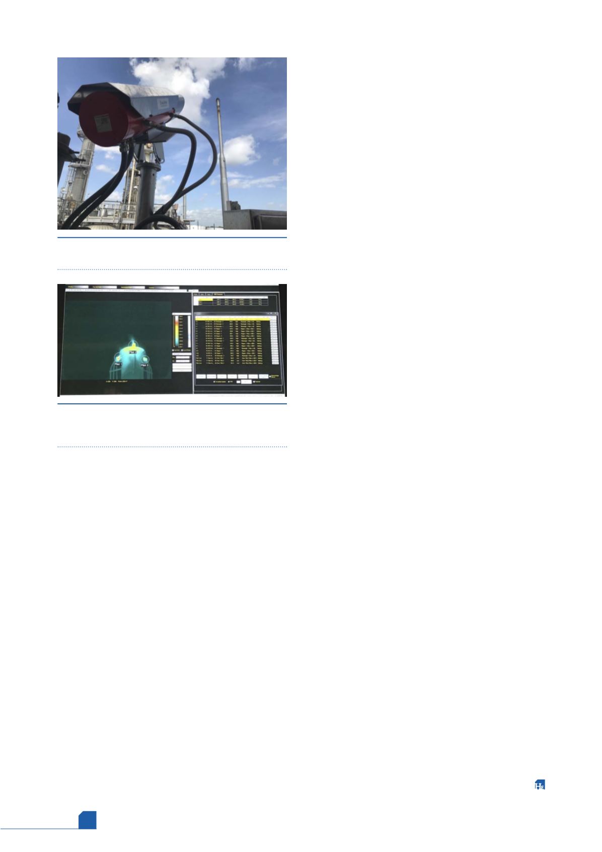
Figure 5.
LumaSpec RT software targeting individual
pilots and providing an independent I/O signal for
each.