July
2020
HYDROCARBON
ENGINEERING
32
For onshore facilities, refineries and petrochemical plants,
continuous flaring has a detrimental impact on the quality of
life of those living in close proximity to production facilities. It is
in these facilities that zero flaring provides the most positive
impact. Flare reduction not only has a positive environmental
impact, but also improves lives. Elimination of routine flaring,
however, does not eliminate the need for a flare. As a key
emergency device, the flare needs to be always available
because the impact of ignition failure could lead to significant
venting of unburned hydrocarbons and the associated health,
safety, and environmental impacts.
With offshore platforms, flaring systems face unique
challenges such as space availability, heat radiation, and noise, in
addition to environmental regulations. Offshore flares need to
deliver high destruction efficiencies, ensure stable flame
patterns across a wide operating envelope, and be designed to
meet the pressure, flow, and gas composition ranges required by
the particular application – often in harsh operating
environments. Achieving zero routine flaring, including no
continuous pilot use, in this operating scenario can be even
more challenging.
Traditional continuously lit pilots and pilot ignition
methods available on the market are not able to ignite and
prove the pilots quickly enough to provide reliable ‘on-demand’
flare pilot ignition.
Zero routine flaring ignition
development
The Zirconium Instant Pressurised (ZIP) ignition system has been
developed by Zeeco in conjunction with Statoil. Statoil was the
inventor of the original pellet systems and holder of the original
patent, and Zeeco’s system is designed around the original
patent. The ZIP systemwas developed for use in process
facilities where instantaneous, safe, and reliable ignition of flare
gas is required. This newly developed ignition system uses a
high pressure pellet propulsion system as opposed to previous
types of low pressure ballistic ignition systems which used
explosive projectiles that had demonstrated safety issues. It also
addresses and designs out many operational issues with the
older systems.
Pellet design
The high pressure pellet ignition system utilises a compressed
nitrogen launching system to propel zirconium-filled pellets
through a guide tube to the flare tip. The nitrogen is used to
provide momentum only to the pellet, and pellet movement
does not rely on the nitrogen filling the guide pipe behind the
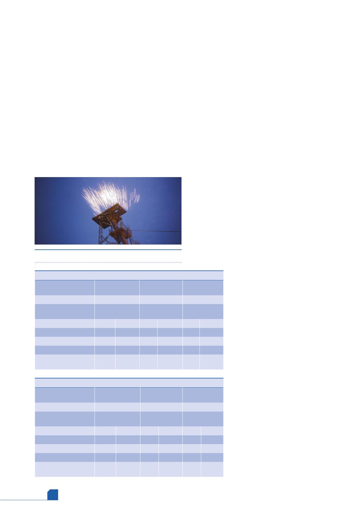
pellet. Upon exiting the guide tube at a high velocity, the pellet
impacts a striker plate, showering the flare
tip exit with sparks and igniting the flare gas
stream. The pellet breaks up on impact,
allowing mixing of the chemicals which
provide the sparks, before being captured in
a fragment bin. No fragments fall to the
ground. The design of the pellet ensures that
the contents of the fragment bin will not be
a danger to personnel. Design changes from
older pellet systems include using pellets
that must be travelling at greater than
140 m/sec. to achieve ignition. This means
that, in normal storage and handling, the
pellets cannot self-ignite and are therefore
safe to handle. Even if dropped or thrown
they will not attain the necessary velocity to
ignite. With no internal explosive materials,
pellets will not detonate if dropped during
normal handling such as loading or fragment
collecting – creating a safer alternative to
low pressure systems on the market.
Propulsion and launching
design
The system utilises a high pressure nitrogen
(N
2
) tank with backup tank to provide a
pressure of 200 barg, and the system
operates on a minimum of 4 barg pressure
nitrogen. It can also operate from a nitrogen
bottle bank. Where high pressure N
2
is not
Table 2.
With pellet ignition system
Flare system
Single 60 in. high
capacity steam tip
Staged multipoint
ground flare
Two 48 in. VariJet
flares
Number of pilots
0
0
0
Annual purge gas
consumption (Nm
3
/yr)
652 412
73 924
53 038
Annual emissions (kg/yr)
NO
X
CO
2
NO
X
CO
2
NO
X
CO
2
Pilots
0
0
0
0
0
0
Purge
751
1 281 435 85
145 199 61
104 174
Steam generation
1074 1 832 630 0
0
0
0
Total annual continuous
emissions (kg/yr)
1826 3 114 064 85
145 199 61
104 174
Table 1.
Flare type comparison
Flare system
Single 60 in. high
capacity steam tip
Staged multipoint
ground flare
Two 48 in.
VariJet flares
Number of pilots
4
15
6
Annual purge gas
consumption (Nm
3
/yr)
652 412
73 924
53 038
Annual emissions (kg/yr)
NO
X
CO
2
NO
X
CO
2
NO
X
CO
2
Pilots
70
119 846 263
449 424 105 179 770
Purge
751
1 281 435 85
145 199 61
104 174
Steam generation
1074 1 832 630 0
0
0
0
Total annual continuous
emissions (kg/yr)
1896 3 233 911 349 594 623 166 283 944
Figure 1.
Pellet hitting striker plate.


