


 49 / 100

Heat-pump compressor continues to operate as it is steam-driven.
Trim condenser fans will stop and trim cooler heat duty would be set to
zero (closure of louvres assumed).
The total relief rate is calculated in Table 9 as follows: [total relief rate
(kg/hr)] = [normal tower overhead flowrate] + [additional flow generated
due to unbalanced heat]. In this case, total relief rate = 58 553 + (
59 864 773/342
)
= 233 596 kg/hr.
The physical properties of the relief stream are shown in Table 10, based
on the data for the tower’s reflux (i.e. the ‘accumulation’ stream at dew
point).
Conclusion
As can be seen from these case studies, the UHM is a quick and simple
method to estimate the relief load from a fractionation tower’s top PSV,
and unlike dynamic simulation, the UHM does not require any special
expertise or extensive data. Only the feed and product composition and
conditions (temperature and pressure at normal operating conditions and
during relief), reboiler and condenser duties and the latent heat of
vaporisation of the accumulation stream at its dew temperature are
required as inputs. The thermal design of the reboiler should be available
in order to properly evaluate overheating in the reboiler due to clean
tubes. The complete system details (e.g. type of overhead condenser and
the mode of control being employed) are required in order to avoid
underestimating the tower relief load.
The UHM may be applied to a wide variety of fractionation towers to
obtain a conservative estimate of the tower relief load. However, it is not
recommended for strippers or those cases where a tower operates near the
critical pressure/temperature. In addition, it cannot be applied to reactive
distillation systems.
Note
The views expressed in this article are those of the author and cannot be ascribed to
Fluor Corp. and/or any of its subsidiaries.
Reference
1. SUARES, D. A. G., ‘A balancing act: part one’,
Hydrocarbon Engineering
, Vol. 24, No. 4,
(April 2019), pp. 35
–
38.
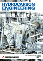
Figure 3.
Relief envelope: P-P splitter equipped with heat pump.