


 54 / 100

August
2019
HYDROCARBON
ENGINEERING
52
technology has immense benefits in terms of cost,
footprint, simplicity of operation, low maintenance
and flexibility, and expansion capabilities over time
(Figures 2 and 3).
Nitrogen generation from membrane
technology
What is a membrane?
A membrane is a permeable barrier that selectively
permits components to pass through it. Membranes
are cylindrical modules consisting of densely packed
hollow fibres. Pressurised, dried and filtered air enters
the membrane module and fast gases such as oxygen
permeate the fibres, leaving behind nitrogen rich gas
at the outlet.
Permeability is a product of diffusivity and
solubility. Diffusivity is how fast a molecule can move
through a membrane whereas solubility is how much
of it can dissolve in the membrane. Also, the
difference in partial pressures between the
components provides the necessary driving force for
separation. From a practical standpoint, operating
pressure, available inlet air flow rate, process
temperature, required nitrogen flow rate, and purity
of application required downstream are key driving
factors for basis of design (Figure 4).
Each membrane module can come in a variety of
different sizes. They are compact and robust, which
makes installation easy. These membranes can be
mounted horizontally or vertically and have a high
operating design life. Membrane technology also has
no moving parts and has excellent operational
flexibility. In addition, Gas Land’s proprietary design
allows and takes into account the anticipated
increases required in LNG plants over time.
Case study 1 – membrane system expansion
and performance evaluation
The following example will consider an existing
system that can be upgraded through the addition of
10 more membranes. Typically, in Gas Land
installations, the customer provides instrument air at
8.62 barg at the inlet nozzle of the system. The
system is sized based on a specific operating
pressure, process temperature, nitrogen flow rate and
purity.
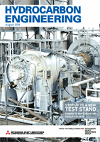
Performance parameters of this system are listed
in Table 1.
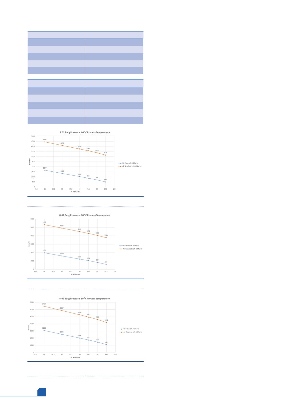
Table 2 shows the performance conditions that
are created by keeping the operating pressure,
process temperature and purity the same when the
system is upgraded with 10 more membranes.
The two tables show that nitrogen output has
been increased by 20% and, correspondingly, the air
required to produce this has also increased by 20%.
Air to nitrogen ratio provides the number of units or
molecules of air required to produce one unit of
nitrogen. Therefore, for this case study and type of
membrane selected the ratio was 2.70. To test design
Table 1.
Performance parameters
Operating pressure
8.62 barg
Nitrogen flow
1647 Nm
3
/hr
Air required
4444 Nm
3
/hr
Nitrogen purity
96%
Process temperature
60˚C
Table 2.
Performance parameters post-upgrade
Operating pressure
8.62 barg
Nitrogen flow
1977 Nm
3
/hr
Air required
5332 Nm
3
/hr
Nitrogen purity
96%
Process temperature
60˚C
Figure 5.
Pre-upgrade performance plot.
Figure 6.
Post-upgrade performance plot.
Figure 7.
Performance plot showing two different design
purity requirements.