


 72 / 100

August
2019
HYDROCARBON
ENGINEERING
70
begin with. Therefore, the reactive power compensation
capability might be more than what the calculations
suggest.
Taking the above example a little further, the next frame
size of drive rating is selected and applied to the sample
1000 hp motor. After working out the calculations, the drive
can deliver a lot more reactive power (776 kVAR) for a small
increase in drive rating. This is beneficial to the end user
since many times it could mean that an entire bank of
capacitors can be eliminated from the system, thereby
increasing the reliability and releasing power capacity in the
plant (Figure 4b illustrates this configuration).
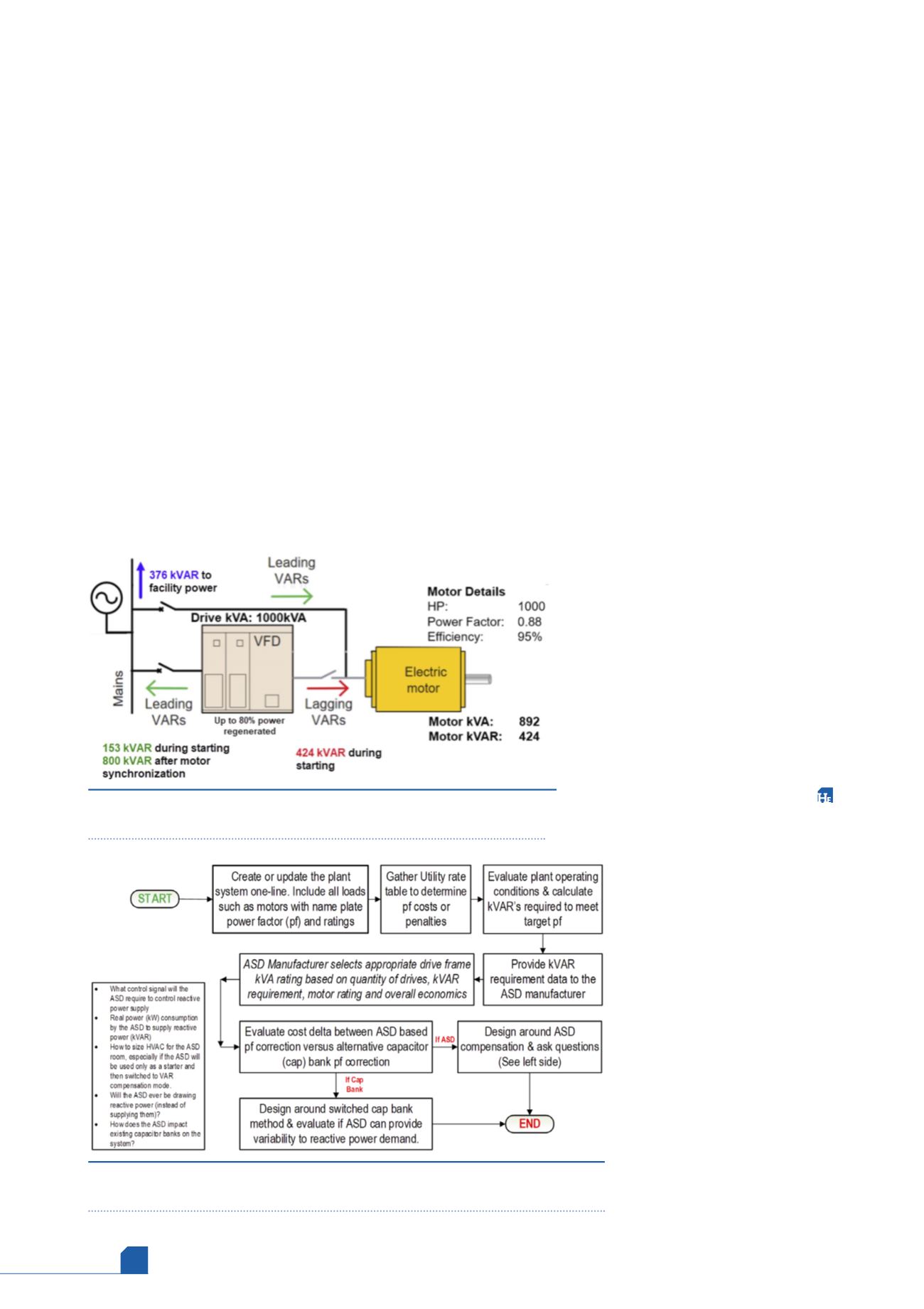
In the industrial world, MV drives are also used solely
for starting large motors. Extending the above example,
consider the case where the ASD is used as a starter for the
motor. Figure 5 shows how the ASD can start the motor,
synchronise with the line, and then compensate for the
motor that it just started. Since the drive is no longer
responsible for running the motor, the net regenerative
capacity of the drive can be used for injecting reactive
power. Hence, the ASD is doing work after starting the
motor, thereby impacting the return on investment
positively for this installation.
Now that the article has described how an MV drive can
help in improving the plant PF, Figure 6 shows an evaluation
chart when planning to apply an MV ASD for reactive power
control at a facility.
Due diligence in gathering the mentioned data and
providing this to the ASD manufacturer will help in selecting
the appropriate drive and its rating. While using ASDs to
provide reactive power is encouraging, a clear understanding
of installation expectations is critical.
Takeaway
Energy savings, soft starting and reduced wear and tear on the
motor have been key motivators for applying MV drives to
large rotating machinery. While standard diode-fed drives
help in improving the motor PF as seen by the utility, they are
unable to do anything better than 0.95 – 0.97 PF. Several
means exist to control the PF in a plant. Switched capacitor
banks have historically been used, but issues with power
system resonance and stability often occur. As power systems
in several western countries become starved of reactive
power availability, due to renewable sources of energy, the
imposition of PF penalties are increasing rapidly. MV voltage
source inverter (VSI) drives with active converter topology are
now readily available to support the voltage,
reactive power demand, and ultimately the
PF. They provide dynamic variability that a
plant might need and can work in concert
with existing capacitor banks. This not only
reduces the maintenance cost associated
with maintaining cap banks but also help in
realising cost savings related to reduced PF
penalties and provide another reason to
utilise an ASD for motor control and energy
efficiency. An MV ASD that can provide
motor and PF control is a convincing piece of
the plant electrical apparatus from an
application, total installed cost (TIC) and
total cost of ownership (TCO) standpoint.
Note
Certain sections of this article were originally
presented at the Institute of Electrical and
Electronics Engineers’ Portland Cement
Asociation (PCA) conference in St Louis,
Missouri, US in April 2019.
References
1. ‘Annual Energy Outlook 2019’, US Energy
Information Administration, https://www.
eia.gov/outlooks/aeo/pdf/aeo2019.pdf.
2. EVANS, P., ‘Power Factor Explained’,
https://theengineeringmindset.com/power-factor-explained/.
3. VERMA, M., PHARES, D., and DICK, B.,
‘Medium Voltage Adjustable Speed Drives:
power factor correction &motor control
– A beautiful combination’, IEEE IAS/PCA
Cement conference, (2019).
4. TMEIC, ‘TMdrive-MVe2 Reactive Power
Control: Exceptional by Design’ https://
www.tmeic.com/sites/default/files/assets/files/library/Exceptional%20-%20
MVe2ReactivePowerControl-D0007-
103Feb2019-web.pdf.
5. SPEAS, T. P., ‘Capacitor Switching and
Capacitor switching devices’, Minnesota
Power Systems Conference (MIPSYCON)
45
th
Annual, (2005).
Figure 6.
Evaluation chart of selecting MV drive vs capacitor bank method of
reactive power compensation and questions to ask.
Figure 5.
Example of using ASD for power factor compensation and as a
soft starter for an electric motor.