


 78 / 100

August
2019
HYDROCARBON
ENGINEERING
76
In an initial process step to produce nitric acid, gaseous
ammonia is mixed with air that has been compressed to
4 – 6 bar by an axial flow compressor.
Air separation units (ASUs) are used for cryogenic
separation of air into oxygen and hydrogen in systems for
the production of fuels and other hydrocarbon products
deriving from natural gases (gas-to-liquid [GTL]) or coal
(coal-to-liquid [CTL]), and also in combined cycle power
stations with integrated coal gasification (IGCC). As these
processes require main air compressors (MAC) with
pressure ratios from 6.5 (low pressure ASU) to 21 (high
pressure ASU), large axial-radial compressors with
intermediate cooling are used.
In the propane dehydrogenation (PDH) application – a
process step in the production of propylene from propane
– axial compressors that compress gas with a lower
molecular weight than air are used beside axial air
compressors.
Axial compressor developments
There were two approaches that essentially determined the axial
compressor development in previous decades: on the one hand,
the main focus was to increase the volume flow without
changes in casing size. As a result, the volume flow was more
than doubled using increased computer capacities and gradually
improved models for calculating fluid three-dimensionally and
determining mechanical stress in the blades. On the other hand,
an improved understanding of axial compressor flow has led to
the blading design becoming even more robust.
A characteristic feature of axial-flow compressors
introduced in the early 1970s is the radial end stage. This stage
undergoes only minor loading in aerodynamic terms and can
therefore be described as a rotating diffuser. The low whirl
component imparted to the flow by the 100% reaction blading
of the rear stages means that this centrifugal impeller can be
arranged directly downstream of the last axial rotor blade row.
The flow is deflected with relatively low loss from the axial into
the radial direction, with velocity being simultaneously
converted into a further increase in pressure. A stator blade
row downstream of the last axial rotor stage is not necessary,
and the need for an axial diffuser is eliminated by the presence
of the radial end stage. This, and the fact that the centrifugal
impeller generates a head equivalent to that of approximately
2 to 3 axial stages, means that the span between the bearing
centres can be kept relatively small for greater reliability in
relation to the rotor dynamics. This compact design not only
results in efficiency advantages, but also has a positive effect
on operational reliability and machine availability.
The radial end stage offers an additional benefit for the
client: the performance map of an axial flow compressor is
limited both by the surge line and by the choke limit or
so-called stonewall effect. The choke limit is determined by
the absorption capacity of the last stage. The compressor then
delivers large volumes at a very low system pressure, so that
operation is on a vertical characteristic line. In the narrowest
cross section of the last stage, sonic velocity is reached,
hindering any further increase in throughput. While the
upstream stages continue to build up pressure, the medium
expands in the last stage against the backpressure of the
process. The resultant pressure surges lead to excitation and
high alternating stresses in this stage. As the last stage of this
axial-flow compressor takes the form of a robust centrifugal
impeller, this mode of operation can be accepted over several
days without problems and without the need for special
protective measures.
The new blading generation
From 2005, it became apparent that customer requirements
demanding ever-greater flow rates and pressure ratios could not
be met by merely upscaling the existing modular range of axial
compressor components. This trend became particularly evident
in ASU applications: medium-term planning of future GTL and
CTL units assumed a daily oxygen demand of 50 000 t or higher
on the basis of economies of scale. According to the above
forecasts, this oxygen demand would in the next step be
covered using compressor trains equipped with appropriate air
separation columns delivering 5000 tpd of oxygen which would
increase to 7000 tpd in a couple of years. For carbon capture and
storage (CCS) applications, similar or even larger compressor
trains are anticipated.
MAC units of this size could no longer be developed using
the existing modular system. Constraints were posed not only by
the feasibility of long rotors in terms of rotor dynamics (at high
pressures), but also by the entire supply chain from raw
component procurement to production, assembly and transport
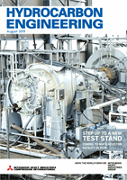
Figure 1.
Development strategy of the MAX1 axial
blading as a hybrid design combining the features of a
gas turbine compressor and an industrial compressor.
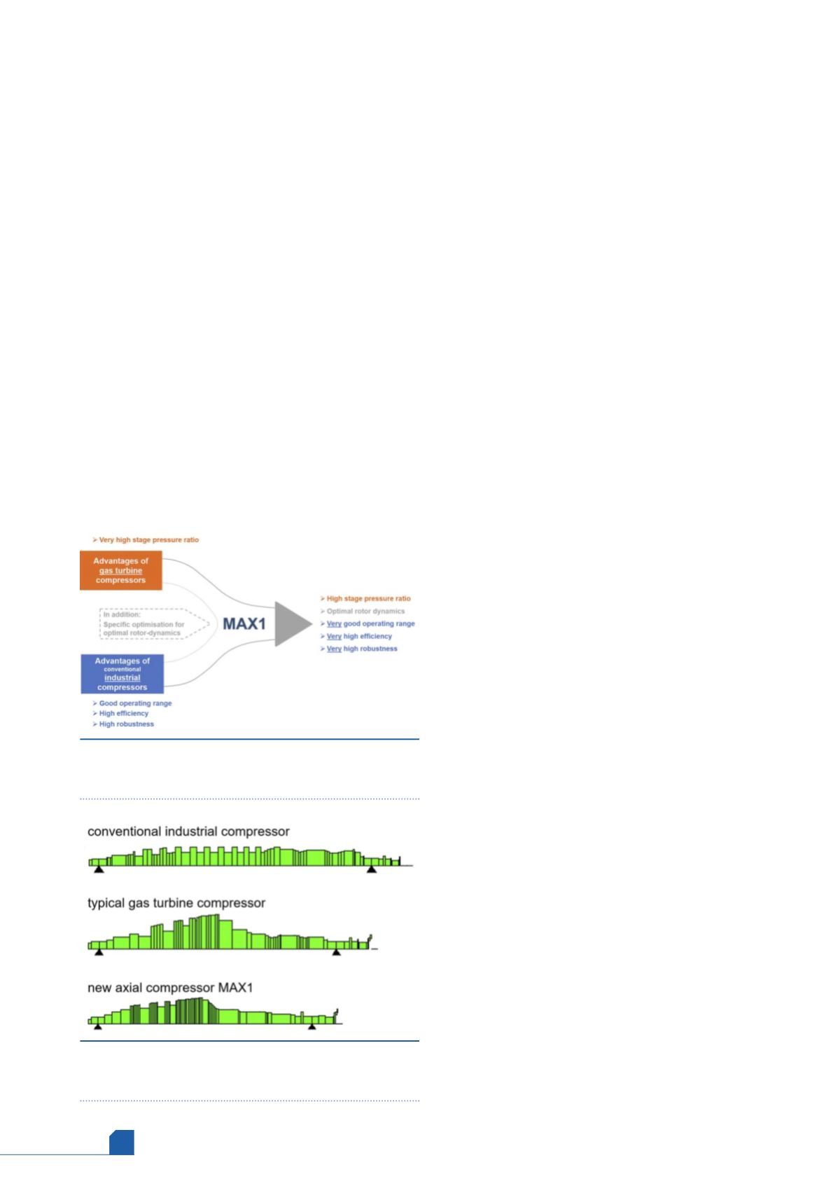
Figure 2.
Rotor dynamic model schematic for various
shaft concepts: conventional industrial, typical gas
turbine and a hybrid design.