


 68 / 100

August
2019
HYDROCARBON
ENGINEERING
66
electronics based rather than rotating machinery based and have
limited ability to deliver the reactive power that is needed to
improve PF. Monetary penalties are imposed in cases where the
plant is unable to meet the PF criteria established by the utility
provider. Hence, it becomes critical for the end user to find
economical ways of generating reactive power within the
boundaries of the plant that consequently improve the overall
PF at the point of common coupling. The scope of the article is
a MV drive (>1000 V) with ASD power ratings ranging from
500 hp to 6000 hp.
MV drives – energy savings
An MV drive converts fixed voltage and fixed frequency that is
available from the utility (e.g. 4.16 kV, 60 Hz) to variable voltage
and variable frequency. By converting from an alternating
current (AC) waveform to direct current (DC) and then back
into AC, the ASD controls not only the voltage but the
frequency of the electric motor. Why is this important?
Equation 1 determines the speed of an electric motor:
(1)
Hence, there are only two ways to change the motor
speed. One can change the number of poles or the frequency.
Once manufactured, the pole number of an electric motor is
fixed. The only option left to control the motor speed is
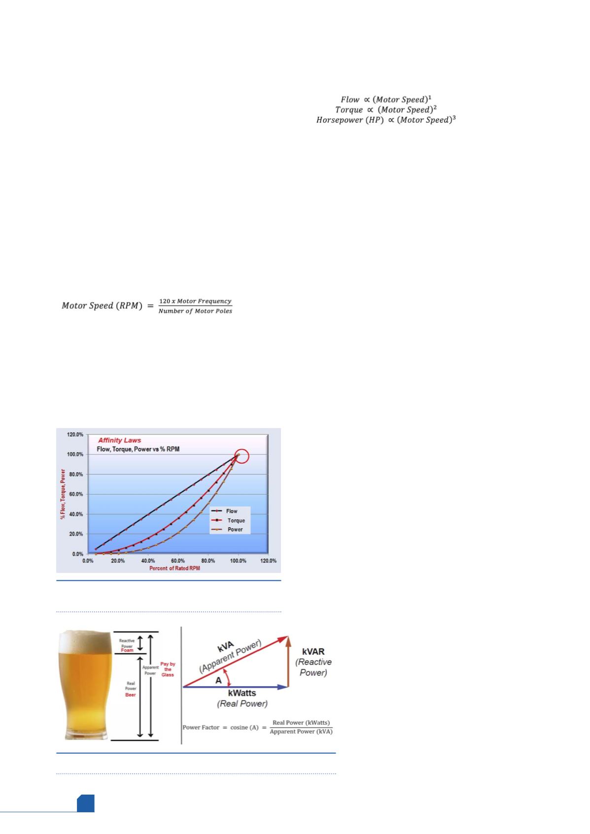
frequency. Variable torque loads such as centrifugal pumps,
fans and, to some extent, compressors (depending on the
molecular weight of the gas) follow affinity laws, commonly
known as 1-2-3 fan laws. From an electrical perspective, the
following holds true:
(2)
(3)
(4)
Consider a pump service in a petrochemical plant. When
the pump is selected, it is designed for the maximum process
capacity (MPC). Hence, the designed flow rate might be higher
than what is currently required by the process. To reduce the
output flow, either a valve can be added to restrict to a desired
flow rate or the pump speed can be reduced, which holds a
linear relationship, as shown in equation 2. For example, if 90%
flow rate is required, the motor can be turned down to 90% of
the nameplate speed. By doing so, the pump not only matches
the flow rate required by the process, but it also reduces the
amount of energy (horsepower) that is drawn by the electric
motor. While several factors such as ASD efficiency, motor
efficiency at part load, percent time the motor is running at
reduced speed, etc., impact the net energy savings, a quick
method to calculate estimated energy savings can be
performed using equation 4. For a 10% reduction in speed, the
energy demand is reduced by ~27% (hp = (0.9)
3
= 72.9% = ~27%
energy saving). Figure 1 plots the flow, torque, and power vs
speed of a variable torque load such as a pump.
MV drives – improving power factor
A simple definition of PF is the efficiency of energy utilisation.
Non-electrical discipline personnel most commonly
understand the principle using the famous beer analogy, as
shown in Figure 2a. In three phase electric circuits, to deliver
real power (W), reactive power is also needed. Reactive power
is the non-working power and expressed in volt-amp reactive
(VAR, kVAR, or MVAR). Inductive loads such as an electric
motor require reactive power to operate.
A further explanation of reactive power and why it is
needed is beyond the scope of this article, but there are a
number of good primers on reactive power and PF.
2,3
However, it
is important to know how real power and reactive power are
related. The power triangle, as shown in Figure 2b, shows the
trigonometric relationship between real and reactive power. The
question that now arises is why an end user or a plant should
strive in reducing if not eliminating the need for reactive power
demand. Wasted system capacity is one key reason. Electric
power generating and delivering apparatus such as generators,
ASDs, and transformers are rated in terms of apparent power
(kVA or MVA) and not real power (kW; see Figure 2b
for relationship). A poor PF requires bigger
equipment, heavier transmission lines, switching
equipment and other power delivery apparatus that
would otherwise not be required in the absence of
reactive power demand. Hence, utility providers
pass on the costs of maintaining larger equipment to
the end user as PF penalties. In fact, in many places
around the world, the end user is mandated by the
utility to maintain a stipulated PF (such as 0.95) at
the point where they are metered, thereby shifting
the burden on to the end user and within the
boundary line of the plant. Using the glass of beer as
an example in Figure 2a – the beer is real power (kW),
Figure 1.
Classical affinity law curve plotting flow,
torque and power vs speed.
Figure 2.
(a) Beer analogy for power factor, (b) power triangle.