


 70 / 100

August
2019
HYDROCARBON
ENGINEERING
68
the foam is reactive power (kVAR). For the same glass, more
beer, less foam would be better.
4
Conventional methods of PF
improvement have been to use switched capacitor banks. In a
paper presented at the Minnesota Power Systems Conference,
T. P. Speas mentioned that capacitors represent an effective
and low-cost method for improving the PF and hence
supporting the voltage on the bus.
5
However, switching
untuned capacitors in and out of the circuit daily presents
challenges with potentially setting up resonant circuits in
parallel with the power system inductive impedance. Recent
advancements in MV drive technology provide a viable
alternative to inject reactive power to the system, thereby
improving the PF. Note that if all reactive power is eliminated
from the plant, then the apparent power is equal to the real
power, and this is known as unity PF (cosine (0) = 1); a goal that
is worth pursuing but might not be economical.
The principle of injecting or absorbing reactive power
(VAR) with an MV ASD is similar in working principle to that of
a synchronous generator. From basic circuits, electric current
travels from a high potential to a low potential. Take, for
example, a synchronous generator. The rotor field winding
excitation current is varied so that the induced stator terminal
voltage is raised or lowered with respect to the connected bus
voltage. If the terminal voltage of the synchronous generator is
higher than the connected bus voltage, reactive current starts
flowing from the generator to the bus and vice versa. Active
front end voltage source inverter (VSI) ASD uses a similar
concept. Figure 3 shows a typical electrical one-line illustration
of an ASD that is set-up to do reactive power (VAR)
compensation while motoring. The ASD converter’s DC bus
voltage (2) is raised with respect to the utility bus voltage to
push reactive power (3) into the drive isolation transformer and
the system. When current flows out to the utility by raising DC
capacitor bus volts, it is effectively reactive current. The
resulting current leads the voltage if the DC bus is higher than
the system nominal and lags if the DC bus volts is less than the
system nominal. The transducer (4) creates a feedback signal to
regulate reactive power (VAR) and PF at the hold point (5),
which is usually the bus or a point higher upstream of the ASD
where the PF correction impacts the most to the end user.
Note that diode front end converter-based drives such as
12-pulse, 18-pulse or 24-pulse, cannot push current back to the
line since they are inherently non-regenerative.
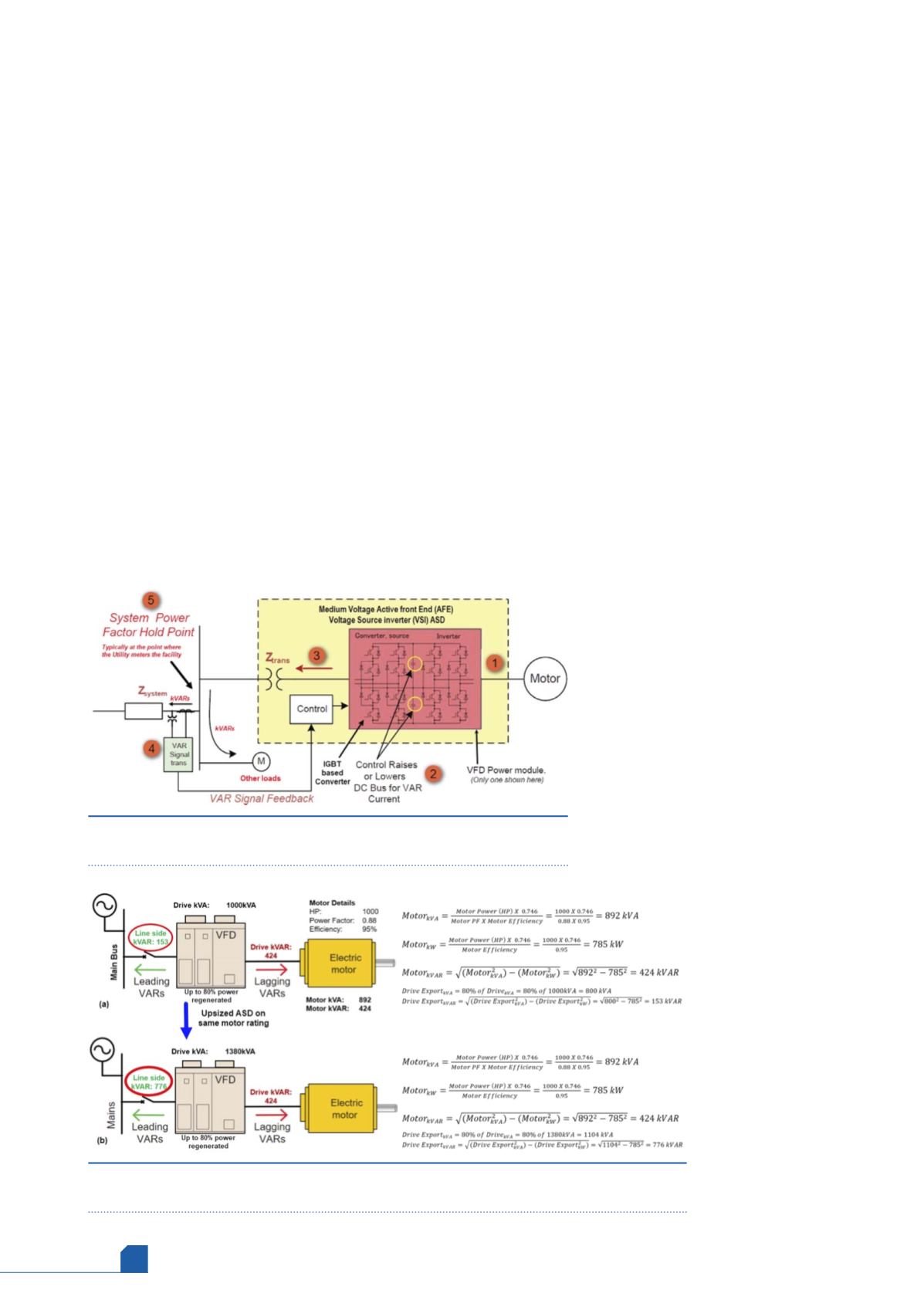
The following example can be used to understand the
practical benefits of an ASD that can inject reactive power
back into the power system. Consider a pump service that calls
for the electric motor to be rated at 1000 hp (Figure 4a). This is
a typical induction motor with a 0.88 PF and 95% efficiency.
The application also requires an ASD for reducing the motor
inrush current and flow control. As mentioned before, ASDs
are rated in terms of apparent power (kVA).
Hence, to run this motor, a 1000 kVA drive
is selected. After doing the power
calculations (Figure 4a), at rated conditions,
the motor requires 424 kVAR of reactive
power. This power is supplied from the ASD
and always takes priority. However, because
the drive is an active front end converter
and has capacitors as the DC link, the drive
can also supply excess capacity back to the
bus as reactive power. ASDs that can push
reactive power to the system are known as
regenerative drives. The amount of
regeneration is limited due to ambient
temperature and the drive power rating. In
this case, the drive can regenerate up to
80% of its apparent
rating (kVA) at 30˚C
ambient. Hence, as
shown in Figure 4a,
the ASD can supply up
to 153 kVAR, assuming
the drive is running at
rated conditions. From
practical experience,
we know that the
prime mover, such as
an electric motor, is
sized 10 – 12% more
than the driven
equipment, and the
selected ASD matches
the motor rating.
Hence, the drive is
usually oversized to
Figure 3.
Electrical illustration of MV ASD for reactive power
compensation.
3
Figure 4.
Example of using ASD for power factor compensation (a) ASD sized for motor
rating, (b) ASD upsized relative to the motor rating.