


 79 / 100

August
2019
HYDROCARBON
ENGINEERING
77
to operation on-site – in short, the technological limits of
conventional industrial axial compressors had been reached.
This urged MAN Energy Solutions to develop a new axial
blading generation under the name MAX1 in cooperation with
MTU Aero Engines: a hybrid axial flow compressor combining the
advantages of conventional industrial compressors (operating
range, efficiency and robustness) with the benefits offered by gas
turbine compressors such as greater power density and thus
higher stage pressure ratios (Figure 1).
The development of the axial blading was based on an
all-new design philosophy with regards to industrial compressor
applications. By means of a multidisciplinary optimisation strategy
during the extended concept phase of the project, a narrow
optimum range could be defined where rotor dynamics, blade
mechanics, aerodynamics and power density were all in their
respective specified target ranges. The flow path design and the
resulting rotor shape clearly show the hybrid approach: a typical
industrial axial compressor has a low stage pressure ratio which
results in a long rotor shaft. In contrast, a typical gas turbine
compressor is characterised by a very high stage pressure ratio. Its
hub contours gradually increase in size when progressing from
the front stages to the rear stages, enabling each stage to achieve
the highest possible circumferential speed. This is necessary so
that the high stage pressure ratio at the compressor exit can still
be achieved at a reasonable performance. Differences between
the various concepts are shown in Figure 2 using simplified
dynamic rotor models. Comparison shows that the new design
approach, also known as hybrid design, represents a compromise
between the two different applications.
With this approach, it was possible to significantly reduce the
overall weight (25% smaller) and total axial compressor length
(30% smaller) as a result of the increased speed by one-third.
Characteristic map measurements of the individual stages
surpassed the results anticipated in the design phase for the
speed and vane-control performance maps. The theoretically
predicted overall efficiency level was confirmed in experiments.
In terms of compressor surge, added robustness due to the new
design proved a substantial improvement compared to previous
axial compressor blade designs: all stress levels measured during
the surge were below the endurance limit. This showed that
MAX1 blades can withstand a vast number of surges without any
blade damage whatsoever.
The MAX1 project marked an innovation in the world of axial
compressors. In the meantime, this new axial blading generation
has been implemented in two axial compressor types. The
axial-radial compressor AR-MAX1 (Figure 3) for standard ASU
pressures has an intercooler between the axial stage group and
the radial stage. The design of the diagonal inlet, the radial stage
and the exit volute were further optimised for this compressor
type in respect to their efficiency, resulting in excellent
performance. For high-pressure ASUs, the modular compressor
type can be expanded to have two intermediate coolers with up
to three radial impellers. The doubling of intermediate cooling
results in energy savings of at least 4% compared to single
intermediate cooling. In view of a trend towards larger and more
energy efficient air separation plants, this concept allows for flow
rates up to 1.5 million m
3
/hr and a production capacity up to
7000 tpd of oxygen. Since the launch in 2011, a total of
19 axial-radial compressors AR-MAX1 have been in operation as
the MAC of an ASU.
Moreover, the MAX1 technology has proved a commercial
success for pure axial compressors (AG-MAX1), used for instance
as a blast furnace axial flow compressor in several iron and steel
industry projects. In this particular application, the surge-robust
design of this axial compressor type is a very important element.
Not only does the 30% increase in rotational speed allow for
reduced axial compressor footprint, it also has an impact on the
configuration of complex compressor trains. Consequently, the
four turbo machines of an in-line nitric acid compressor train are
typically arranged on two separate base frames: the steam
turbine and the NO gas compressor are mounted to the one
frame, whereas the second frame incorporates the axial flow
compressor and tail gas expander. The two train elements have
different speeds and are connected together via an intermediate
gear unit as a result. This is because efficient radial compressor
operation is only possible at a high speed given the low flow rate
of the NO gas and a pressure ratio of about 3, whereas the axial
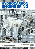
Figure 3.
Axial-radial compressor AR-MAX1.
Figure 4.
AG-MAX1 as a component of the NAMAX
modular nitric acid train package.
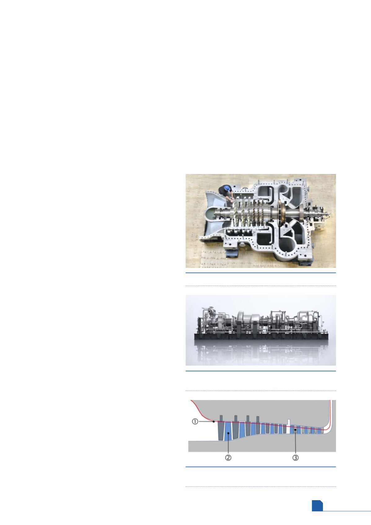
Figure 5.
MAX1 FlowCut: (1) modified flow path (2) cut
rotor blade (3) cut stator blade.