


 62 / 100

August
2019
HYDROCARBON
ENGINEERING
60
significant amount of C
1
– C
4
mercaptans.
Other components detected included
heavier hydrocarbons including benzene and
toluene as well as minor amounts of dimethyl
ether and acetaldehyde. The sample as
analysed also included some of the feed gas
components, mostly methane, ethane and
propane.
The heavier hydrocarbons and
mercaptans at the low process temperature
likely contributed to MCHE fouling. The
presence of heavier hydrocarbons also
suggested that the upstream HRU was not
operating effectively. In fact, analysis of this
small sample of liquids collected during
testing was the strongest evidence of the
root-cause of MCHE fouling and led to
activities directed at verifying HRU
operation.
Mitigation strategies and
process improvements
The MCHE contamination causing fouling and
freezing issues was identified as heavy
hydrocarbons and mercaptans. The
mercaptans were determined to be
originating from the molecular sieve beds.
Small concentrations of mercaptans in the
feed gas to the beds likely built up slowly
over time until the sieves were saturated and
began to release contaminants during
regeneration. Due to the closed system
design, mercaptans could only be released in
the treated gas over time. The heavy
hydrocarbons were present because of
inefficiencies at the upstream HRU. This
problem was identified only because of the
contamination found during gas testing at the
MCHE inlet. Operations were adjusted to
prevent reduced efficiency at the HRU after
an upset and mitigate MCHE fouling.
After addressing the root-causes for
fouling at the MCHE, solutions were
established considering all the data and
observations. Changes to the HRU operation
solved the fouling at the MCHE. Central to
the success of this onsite work was the
rigorous sampling and testing of
contaminants coupled with process data
analysis and investigation.
Overall, it is important to understand that
the contamination testing and control
strategies for any process unit is a critical step
for ensuring a stable and reliable plant
performance. The majority of plants that do
not consider this important step carefully are
often challenged with high operating costs,
low equipment reliability, unscheduled
shutdowns, and other adverse situations with
direct impacts on plant economics.
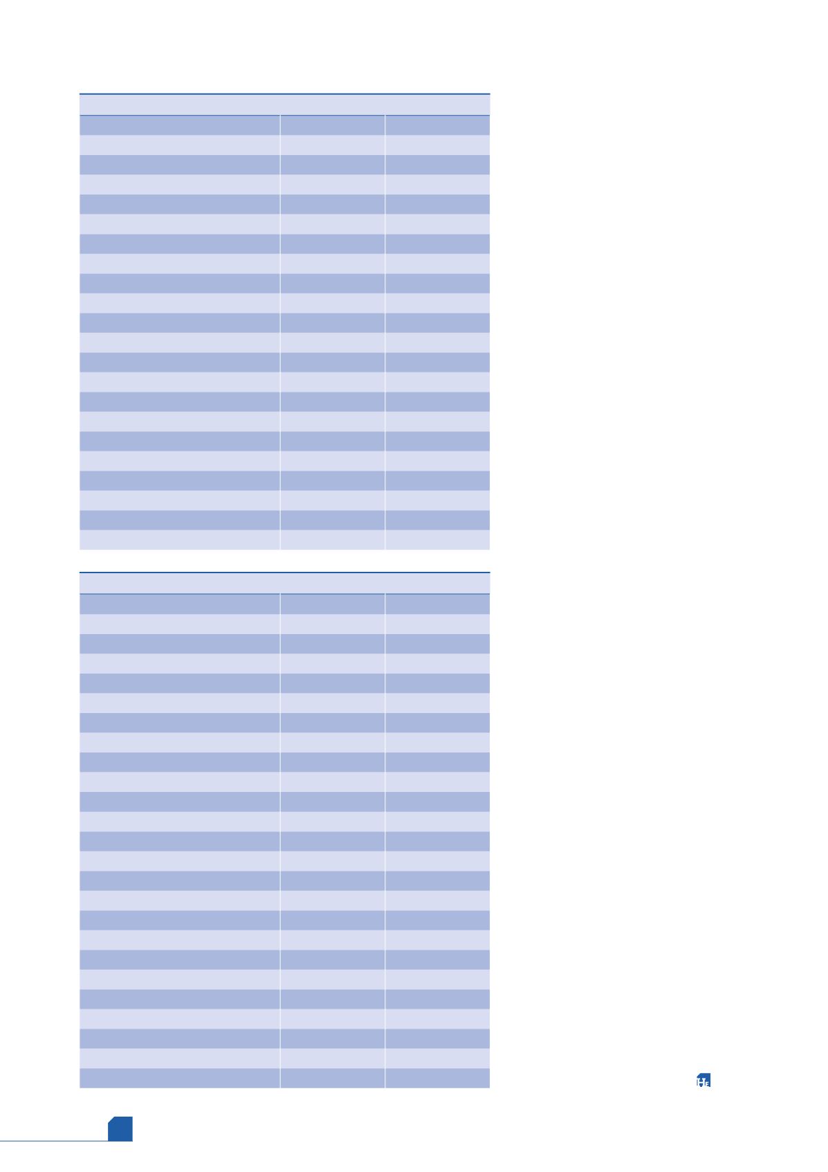
Table 3.
MCHE inlet contamination analysis results (liquid phase)
Component (liquid phase)
Concentration
Units
Helium
<0.0010
% mole
Nitrogen
0.1221
% mole
Carbon dioxide
<0.0050
% mole
Oxygen
<0.0050
% mole
Methane
38.6956
% mole
Ethane
17.1773
% mole
Propane
25.9707
% mole
Iso-butane
3.4366
% mole
n-butane
6.6348
% mole
Iso-pentane
1.8470
% mole
n-pentane
1.1454
% mole
Total hexanes
12579
ppm (v/v)
Total heptanes
10611
ppm (v/v)
Total octanes
15461
ppm (v/v)
Total nonanes
11054
ppm (v/v)
Total decanes
<1
ppm (v/v)
Benzene
173
ppm (v/v)
Toluene
1016
ppm (v/v)
1,3-dimethylbenzene (m-Xylene)
<1
ppm (v/v)
1,4-dimethylbenzene (p-Xylene)
<1
ppm (v/v)
1,2-dimethylbenzene (o-Xylene)
<1
ppm (v/v)
Table 3.
MCHE inlet contamination analysis results (gas phase)
Component (gas phase)
Concentration
Units
Hydrogen sulfide
<0.1000
mg/m
3
Carbonyl sulfide
<0.1000
mg/m
3
Methyl mercaptan
16.1400
mg/m
3
Ethyl mercaptan
315.4200
mg/m
3
Tert-butyl mercaptan
445.6300
mg/m
3
n-propyl mercaptan
788.7800
mg/m
3
Isopropyl mercaptan
119.0900
mg/m
3
n-butyl mercaptan
96.3700
mg/m
3
Methanol
<0.5
mg/kg
Dimethyl ether
27.8000
mg/kg
n-propyl alcohol and isopropanol
<0.5
mg/kg
Acetone
<0.5
mg/kg
Acetaldehyde
2.8
mg/kg
Isobutylaldehyde
<0.5
mg/kg
Butylaldehyde
<0.5
mg/kg
Helium
<0.0010
% mole
Nitrogen
0.2432
% mole
Carbon dioxide
<0.0050
% mole
Oxygen
0.0070
% mole
Methane
70.1234
% mole
Ethane
15.5826
% mole
Propane
11.5456
% mole
Iso-butane
0.8563
% mole
n-butane
1.2976
% mole